This is a story about designing and building a replacement controller board for a USB keyboard. The source code and hardware design files are available on github.
IntroductionTop
In general, I tend to avoid any Microsoft products, the one exception was my keyboard. I have been using the Comfort Curve 2000 keyboard for several years and got quite used to it. Unfortunately, its electronics board got zapped with 230V in an accident involving a crappy chinese power supply.
What do you do when your keyboard breaks? Buy a new one. The problem is that I've grown really used to my keyboard. Unfortunately, this model is no longer manufactured - and nobody bothers to sell replacement parts for an old consumer-grade keyboard, so I decided to fix it myself. Also, it was a good excuse to play with some hardware development :)
Keyboard basicsTop
Most computer keyboards have a small PCB with controller electronics (with a PS/2 or USB interface) connected to the key matrix. The matrix itself is printed on two layers of flexible plastic sheet. Individual keys are addressed with a row and column number (not necessarily related to the physical key row/column layout). When a key is pressed, it makes an electrical connection between one column and one row of the matrix.
Note that the rows/columns are physically equivalent, and so these terms are interchangeable.
This animated schematic shows a section of a simplified keyboard. The keys follow a QWERTY layout for illustration purposes, a real keyboard will most likely have a different key matrix layout. As seen in the picture, the controller periodically scans the matrix by applying a voltage to each of the rows in sequence and checking which columns show the expected voltage level. The controller "knows" the key matrix layout, so that when row 0 is scanned it expects that a signals on the columns represent the keys Q,W,E,R.
My keyboard is arranged in a 8 x 18 matrix. It came with a USB interface, and for my replacement, I decided to stick with USB as well.
Building your own keyboard controllerTop
I've had some experience with AVR microcontrollers. The low-end ones don't have hardware USB support, but with clever programming, firmware-based low-speed USB is possible. Fortunately, all the cleverness is available in an easy to use package - V-USB by objective development. The library comes with many example programs, some of which work by emulating a USB keyboard - exactly what we need.
The microcontroller for this project needs to have at least 8 (matrix rows) + 18 (matrix columns) + 3 (LEDs) + 2 (USB data) GPIO pins. Also, a SMD part is preferred due to limited space inside the keyboard. ATmega16 seems to be the smallest part to satisfy these requirements.
Circuit designTop

The circuit is based on the V-USB example circuit, utilizing an LDO voltage regulator which reduces the 5V from USB to 3.3V for the AVR. The microcontroller is slightly overclocked or undervolted (by design it runs up to 16MHz above 4.5V, or up to 8MHz on lower voltages), but in practice it works fine. The lower working voltage is required to allow the AVR to directly interface with 3.3V USB signaling.
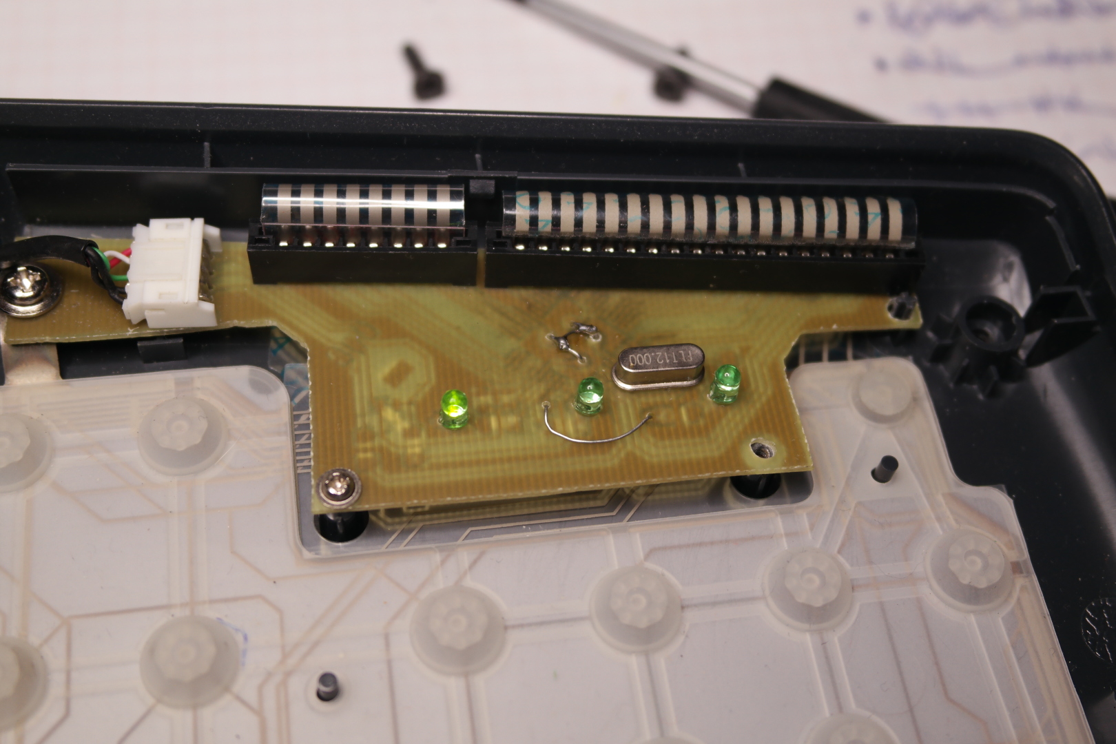
Pins D2 and D3 (INT0/INT1) are connected to the USB signal lines as required by V-USB. The rest of the circuit consists of the keyboard matrix connectors and Num/Caps/Scroll lock LEDs. The reset pin is exposed on a separate pad to allow ISP programming (see ISP programming).
Since the keyboard matrix will be decoded in software, we can reorder the rows and columns arbitrarily. Because of this, the matrix connectors are wired to AVR pins according to the physical layout of the pins in the TQFP44 package, not the logical pin numbering. This results in a slightly convoluted circuit schematic, but much simpler PCB routing.
PCB designTop

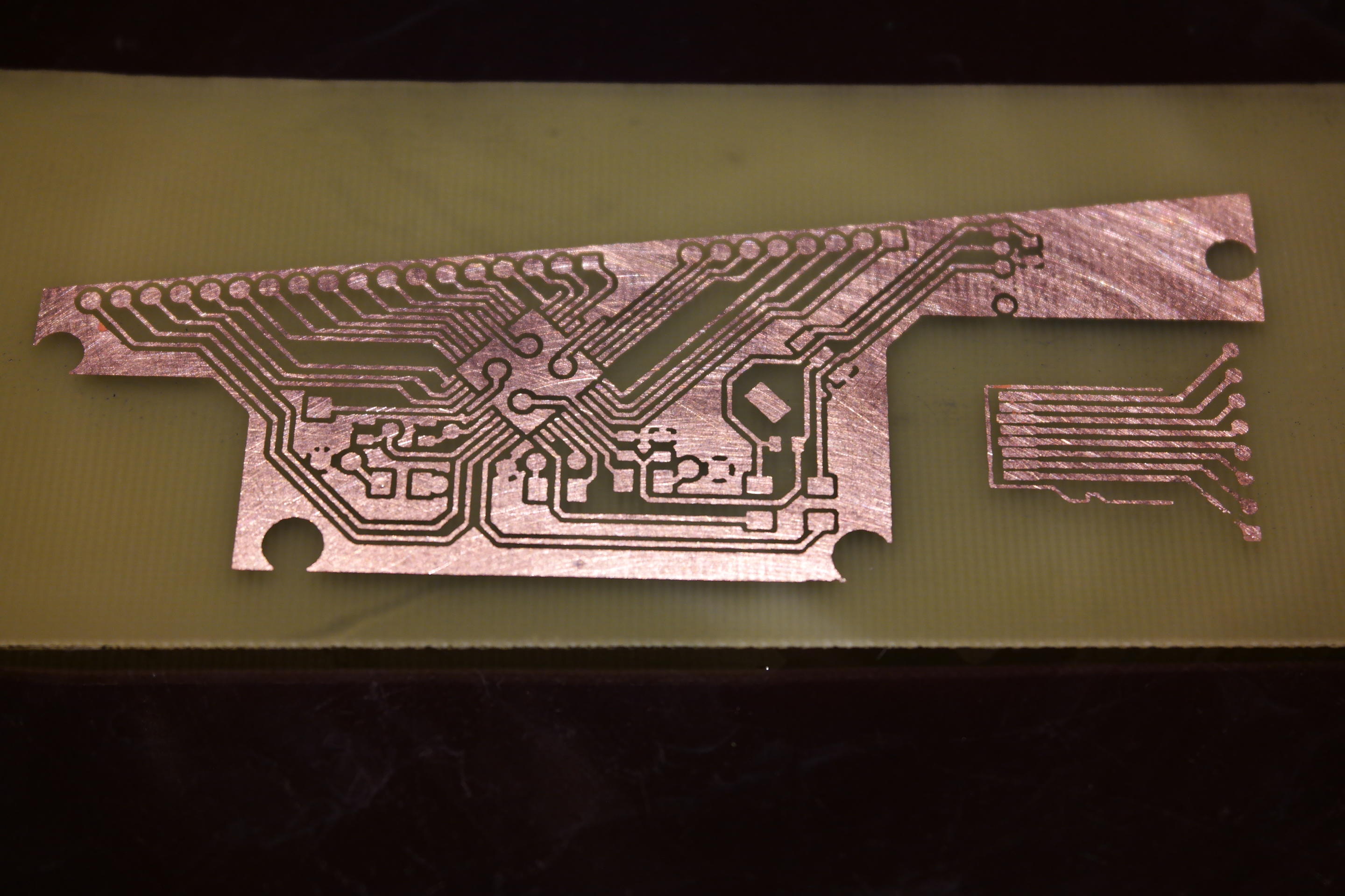
The board layout is relatively simple, allowing for a single-layer PCB with few jumper wires. For quick and accurate measurements of the original board, I've scanned it in a flatbed scanner. This allowed me to easily place the important elements (connectors, LEDs, mounting holes) in the appropriate locations.
The board was produced at home with the toner transfer method. To accommodate for low precision, the PCB tracks were made as wide as reasonably possible (15 mils). The connectors were salvaged from the original board. Please ignore the additional part on the photo of the uncut PCB - it is for an unrelated project.
Now, to the software.
ISP programmingTop
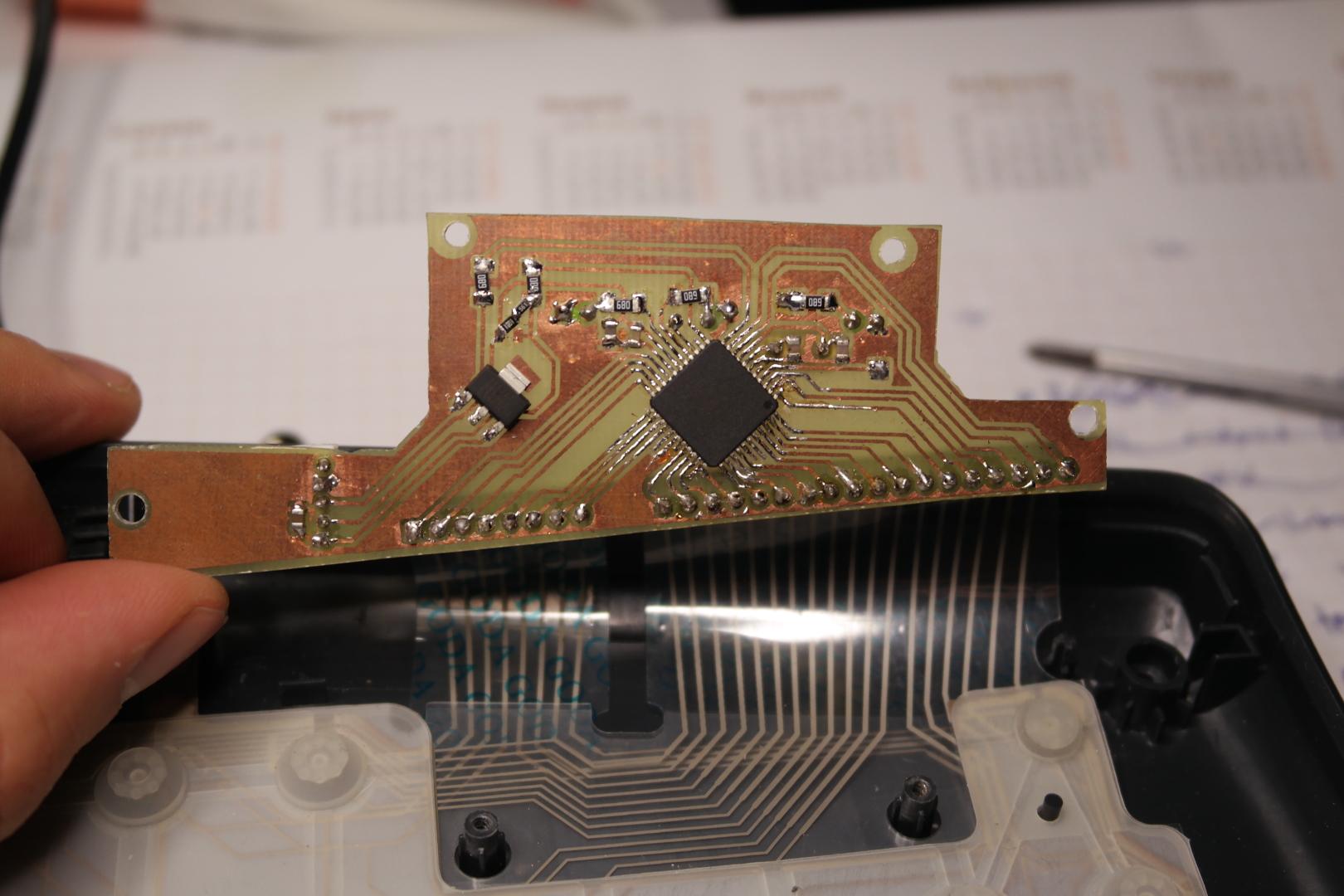
You might have noticed that the board doesn't include a programming port. I could program the microcontroller before soldering it, using a TQFN44 programming socket (which I don't have). Instead, I've soldered several wires to the back side of the keyboard matrix header, to the pins corresponding to MISO, MOSI, and SCK of the AVR. The reset pin was also exposed on a separate pad on the PCB for soldering a temporary programming wire.
With Reset, MISO, MOSI and SCK brought out from the board, along with power lines, ISP programming is straightforward... unless you want to actually use the keyboard. To make a compile-program-test cycle as easy as possible, I've programmed a small bootloader into the microcontroller - AVRUSBBoot, also based on V-USB. The bootloader allows for self-programming the AVR using the USB connection.
I've configured the AVR fuses to run the bootloader at power-up. When the bootloader runs, it checks if a specific key is pressed on the keyboard, or if the AVR reboot is the result of watchdog overflow. If none of the conditions are met, it proceeds to run the main executable. On the other hand, if a key was held during powerup, it starts in the self-programming mode. The main executable can also return to the bootloader by triggering a watchdog reboot.
After the bootloader was complete, I've removed the extra wires, connected the keyboard matrix and started working on the main keyboard controller firmware.
Firmware: USB HID basicsTop
USB keyboards use a so-called Human Interface Device protocol over the USB layer. It basically works like this:
- The host (PC) reads a set of "descriptors" from the device (keyboard) which describe what kind of inputs/outputs it reports
- The host periodically polls the device for updates and reads new data in the form of "reports"
- The host can also explicitly read the device status ("report") and send its own kind of reports to the device (for example toggling the LEDs on a keyboard).
As a base for my firmware, I used HIDKeys, one of the convenient V-USB examples. The example implements the USB keyboard protocol, the most important missing part was scanning the keyboard matrix.
My firmware supports an additional "vendor-specific" command which triggers a reboot-to-bootloader. This allows for easier firmware updates, otherwise I would need to replug the keyboard and trigger the bootloader manually.
Key ghostingTop

The animation shown here illustrates a problem inherent in the design of a simple keyboard matrix. When multiple keys are pressed, the current can flow through some of the keys in the opposite direction (key "D" on the picture). This way, some key combinations may cause additional "ghost" keys to be reported. When the controller scans row 0, key "E" is correctly reported on column 2. Because "D" is also pressed, the current can also freely flow into the whole row 1, and through "A" into column 0. This - falsely - indicates to the controller (which believes that only row 0 is active) that the "Q" key was also pressed.
Now, this would seem like a theoretical problem - aside from gaming - who would press so many keys at once? Well, During my tests I noticed that when typing "ls -l" fast enough, I actually was pressing the dash key while still holding 's' and space, and this particular key combination made the keyboard to register an additional keypress (the dot key).
The problem is called "key ghosting" and the "correct" solution is to place a diode in series with each switch. This ensures that current can flow only in the desired direction (row -> column). Of course, consumer keyboards are too cheap for this. Instead of preventing key ghosting they are designed to detect it and defer reporting on the problematic part of the key matrix, waiting until the problem resolves itself (user releases keys). Also, modifier keys are strategically placed in the "least conflicting" areas of the key matrix.
Key ghosting: detectionTop
While the key ghosting problem is widely known, I failed to find any well-known solution for easily detecting the ghosting condition. Anyway, half of solving the problem is to define it properly, so here we go:
- A triplet of keys can be problematic if they form a "right triangle" on the key matrix. That is, one of the keys (like "D") shares a row with one of the others ("A"), and shares a column with the third one ("E")
- Such a triplet can be defined equivalently as follows: a row has two (or more) keys pressed and one of the columns corresponding to these keys has also a key pressed for a different row. This definition also works if we swap rows/columns.
- A problematic triplet will most likely be detected as a "quadruplet" (together with "Q" in the example). The only way in which only three problematic keys would be detected is a "transient" effect when a key is pressed or released between the scanning of two rows.
- We can't detect which of the four keys is the "ghost", so the only sensible solution is to revert to the previous state
- While key ghosting is in progress, unrelated columns and rows can be properly handled.
My solution works as follows:
- The "clean" state (without any ghosts) of the full keyboard matrix is stored in the controller's RAM.
- During the polling loop, the current state of the keyboard matrix is scanned into a separate array in RAM.
- The current state is scanned for the problem condition: for the implementation details please see the source code. In result, we get a mask of the problematic rows and columns.
- Parts of the current state not covered by the masks are copied into the "clean" state
- Finally, the "clean" state is reported to the host.
Multimedia keys supportTop
The basic USB HID protocol mentioned earlier allows for a basic alphanumeric keyboard to be implemented. My keyboard has 10 additional "multimedia" keys not covered by the standard "keyboard" scancodes. These special keys are reported as "Consumer Devices/Consumer Control", whatever this means (see the USB standards). This means that the HID report descriptor needs to be extended.
A common report format for keyboards consists of 8 bytes: 1-byte bitfield for modifier keys, one reserved byte and up to 6 bytes representing non-modifier keys. My first attempt was to extend the report format from the standard 8 bytes, to make space for the special-key reports. Unfortunately, it seems that V-USB only supports USB packets up to 8 bytes on the interrupt endpoint. Fortunately, the USB HID protocol is flexible enough to work around this problem. I can define multiple variants of the report, differentiated by the first byte (Report ID).
- The "classic" key report, slightly adjusted: 1-byte report ID (=1), 1-byte modifier keys (bitfield), 6 bytes non-modifier keys
- The "multimedia" key report: 1-byte report ID (=2), two-byte multimedia keys (bitfield)
For generating the HID report descriptor I used the ugly windows-only "HID Descriptor Tool" from the USB.org page.
USB Remote WakeupTop
Most USB keyboards feature USB Remote Wakeup - a special signalling mode used to "wake up" the host computer from suspend. V-USB doesn't provide any special support for this feature, instead it needs to be implemented by the application (my) code.
The implementation is mostly straightforward:
- The USB configuration descriptor needs to have a flag set to notify the host that the device can initiate wakeup.
- The USB suspended state needs to be detected. In order to do this, I use V-USB's usbSofCount feature, which allows me to determine if the host is sending SOF (Start Of Frame) markers or not. When no SOF markers are received for a prolonged period of time, the USB bus is assumed to be suspended.
- During suspend, the keyboard keeps polling its keys. If a key press is detected, we trigger the USB wakeup signal by overriding V-USB and manually pulling the D+ and D- lines low for a predefined period of time. Then we return control to V-USB.
TODO: usb boot protocolTop
Most BIOS implementations use a simplified driver for USB keyboards, utilizing so-called USB Boot protocol. The boot protocol uses a predefined 8-byte report descriptor, which differs from my custom descriptors. The original firmware I was using had some provisions for the boot protocol, but I haven't maintained them during development, so the boot protocol support is currently broken.
Similiar projectsTop
These projects also seem to implement a keyboard controller. Of course I found them only after completing most of my implementation:
I know there is a global variable usbSofCount. But for which condition did you check?
Or is your code available somewhere?
Thanks!
Thanks for sharing