IntroductionTop
At my workplace, we've bought a LED matrix panel from China, with the usual amount of documentation (none). The board has some identifiers such as HUB75-E or XR1.875-128X64-1515-32S-4L-V3.0. Despite my best attempts, I haven't found any working code which could drive this panel, so I had to dig in a little deeper.
Identifying componentsTop
The board seems simple, and I'm too busy to draw a schematic right now, so you'll have to suffer my written explanation instead.
-
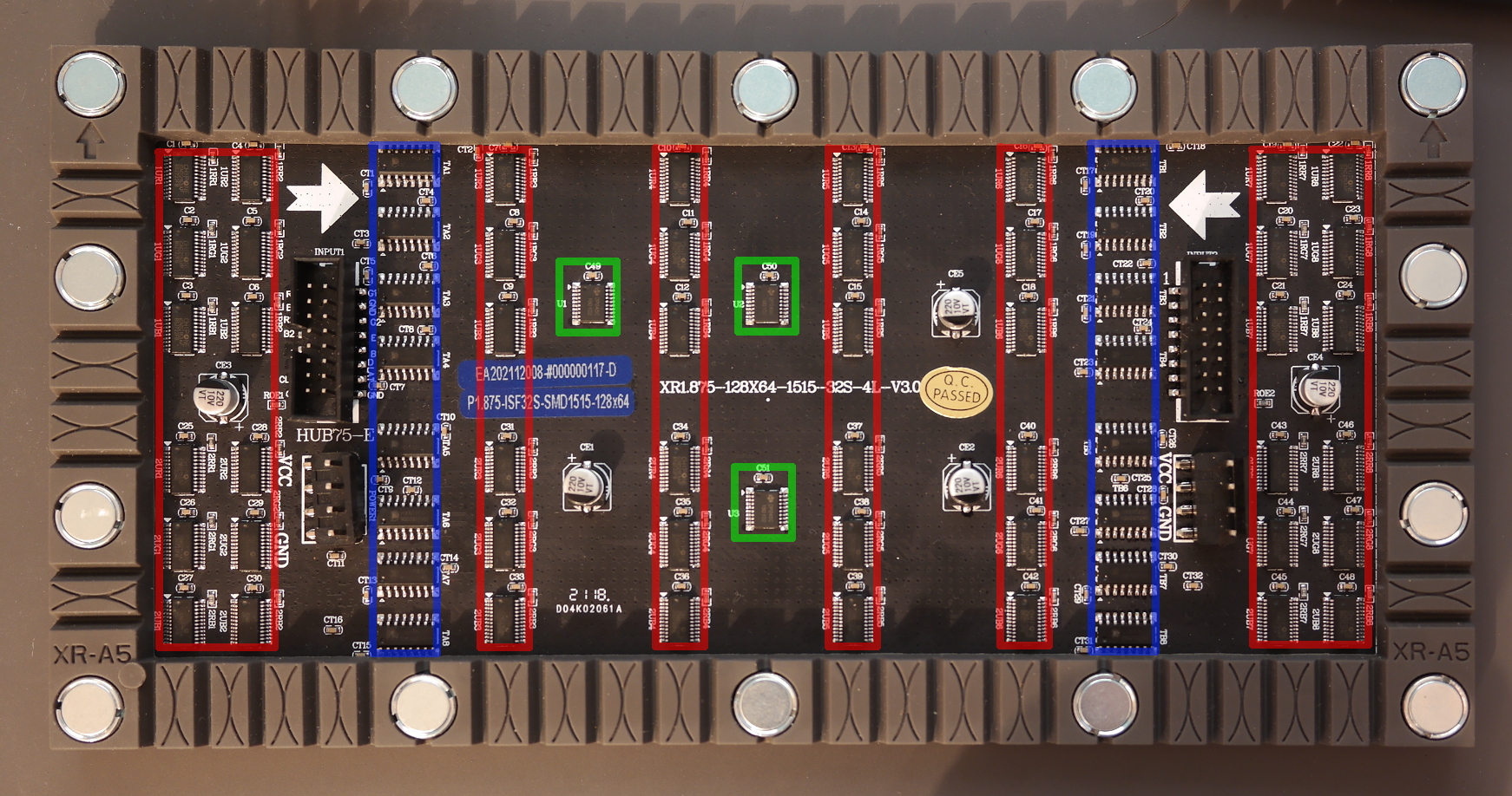
The large pin header has nice and seemingly helpful labels. Spoiler alert: some of these are wrong.

- Signals from the pin header is routed to the buffer chips (marked DP245C, likely some 74HC245 clone) - marked green on the photo above.
- Buffered RGB/CLK/LAT/OE signals are routed to column drivers marked red (ICND2153).
- Buffered A/B/C signals are routed to row drivers marked blue (HX6158SP).
What this panel isn'tTop
In usual LED matrix panels, the column driver is a simple shift register with latch, and the drivers are chained together to form a shift register as wide as the panel. The row drivers are simple N-to-M decoders, this is a 1/32-scan panel, so these would be 5-to-32 decoders. The panel is logically split into two 128x32 halves, with common row drivers and separate R1,G1,B1 (top) / R2,G2,B2 (bottom) signals.
With a regular panel, the driver shifts in a full row of pixels into the shift registers, latches the data in, outputs the row index on ABCDE pins and sets OE to activate the row drivers. One row of LEDs lights up, and the driver board can begin shifting the next row. This continues until the full panel is scanned, for the next frame data needs to be supplied again by the driver board. There is no intensity control, so if you want more than 8 colors, you need to supply the frames fast enough to give an illusion of higher color depth - normally this requires a very high driving frequency.
So what is it?Top
This panel is different. For one, the column drivers - ICND2153 (datasheet) are "16-channel PWM constant current LED sink drivers". The datasheet isn't very specific, but long story short, this chip has a builtin 16-bit PWM generator and enough RAM to store data for 16x32 array of LEDs (monochrome). This makes it possible to have the LEDs refreshing with a high frequency, while the data is supplied more slowly (or even paused?). For this to work, the OE signal is replaced with GCLK, a reference clock for the PWM generator. Also, some "magic" latch/clock sequences are used to "tell" the driver which row is being driven and some other configuration. I don't know how, but someone from YT channel "Electronics in focus" managed to drive a compatible driver (ICN2053) and released their code here. This was invaluable in my work with this panel. I wouldn't have guessed the initialization sequences. This being said, this code didn't quite work with my panel. Only half of the lines were active and the output was messed up.
The row drivers are even more mysterious. As you might have noticed, the D/E signals aren't used anywhere on the board. The chips - HX6158 (manufacturer website, datasheets are 404) are "8-channel LED display line switch PMOS chip" according to machine translation from Chinese. There is exactly zero information on these on the whole Internet as far as I know.
HX6158?Top
A more careful analysis of the board reveals that the HX6158 chips have 8 outputs each, and the 'C' signal (as it's called on the board silkscreen) is not routed to each one directly, but in each group of four the output of one chip is chained to the next one. After some blind testing and head scratching this turned out to be another shift register. See my idea of the pinout below:
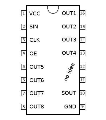
The 'C' signal from the pin header is actually serial data input for the row drivers, 'B' is output enable (active low), and 'A' is the clock for row drivers. Subsequent row drivers receive the serial output from the previous driver, while OE and clock signals are routed to all in parallel.
With this information, driving the rows is reasonably straightforward:
- At the beginning of the frame, shift in one '1' on the 'C' input
- For each row, supply one clock on the 'A' input
- 'B' should be used to enable/disable the row drivers when the column drivers are switching their outputs. That's my guess anyway, so far I've been keeping 'B' low all the time, and I'm already getting useful images out.
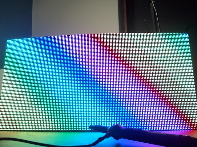
The two pixels in the top row are physically broken, this is a flexible panel and I might have flexed it a bit too much :)
Code?Top
I'm sorry to say that I won't be making a full source code release now. But if you're motivated enough, the snippet below should be enough :)
void IRAM_ATTR icn2053_scan_next()
{
    if(scan == 0) {
        icn2053_SetScan(4);
        icn2053_SetScan(5);
        icn2053_SetScan(4);
        icn2053_SetScan(0);
    } else {
        icn2053_SetScan(1);
        icn2053_SetScan(0);
    }
    scan = (scan+1)&31;
}
This code goes into icn2053.c from the icn2053_esp32_demo repository linked above.