STM8 microprocessors utilize a proprietary (but well documented) programming protocol called "SWIM". The usual way to program these is with a ST-Link programmer. Without such luxury at hand, I managed to talk to the SWIM interface using a Raspberry Pi's SPI interface, one transistor and one resistor. Of course, it would be simpler to just buy an ST-Link, but that's not the point :)
Here's the source code if you're interested.

STM8 SWIM protocolTop
The programming (and debugging) protocol for STM8 is documented on the manufacturer's website. The flash programming manual is also relevant. If you are interested in the details, go ahead and read these. I will try to describe the essentials here.
To quote from the document, "The SWIM is a single wire interface based on asynchronous, high sink (8mA), open-drain, bidirectional communication". In other words it uses one bidirectional pin with a pull-up resistor which is driven low by either the STM8 or the debugger. SWIM communications are synchronized to the STM8's SWIM clock, which defaults to 8MHz (regardless of the clock source of the microcontroller). Data bits are transmitted with a sequence of low/high pulses on the SWIM line. For example, in the "low speed bit format":
- transmitting a 0 means pulling the SWIM line low for 20 SWIM clock lengths (2.5us), followed by releasing the line for 2 SWIM clocks (0.25us)
- transmitting a 1 means pulling the SWIM line low for 2 SWIM clock lengths (0.25us), followed by releasing the line for 20 SWIM clocks (2.5us)
On the receiving side, the signal is decoded as a 0 bit if the low signal exceeds 9 SWIM clocks, or 1 otherwise.
| data bit | idle | 0 | 1 | idle | ||||||||||||||||||||||||||||||||||||||||||||||||||||
|---|---|---|---|---|---|---|---|---|---|---|---|---|---|---|---|---|---|---|---|---|---|---|---|---|---|---|---|---|---|---|---|---|---|---|---|---|---|---|---|---|---|---|---|---|---|---|---|---|---|---|---|---|---|---|---|---|
| time [us] | 0 | 1 | 2 | 3 | 4 | 5 | 6 | |||||||||||||||||||||||||||||||||||||||||||||||||
| SWIM line | 1 | 0 | 1 | 0 | 1 | 1 | ||||||||||||||||||||||||||||||||||||||||||||||||||
Most of the high-level operations are defined as sequences of these bits, there is also the "entry sequence" which consists of slower signalling.
Any device implementing this protocol needs to read/write the SWIM line quickly (8MHz resolution) and with predictable timing. A bit-banging implementation would not be practical on a Linux-based board (like the Raspberry Pi), because meeting the timing requirements could be difficult (feel free to prove me wrong :).
(ab)using SPITop
SPI, or Serial Peripheral Interface is a simple serial protocol for inter-IC communications. In its most basic form, two devices communicate using three serial lines: SCLK, MISO and MOSI (CS - chip select is not very interesting for our purposes). One of the devices, designated as the "master", generates the clock signal (SCLK). During each cycle of the clock signal, both of the devices send and receive one bit of data, master transmits on the MOSI (master out, slave in) line, slave transmits on the MISO (master in, slave out) line. Usually, the sequence of bits is interpreted in packs of 8 (bytes), with the most significant bit transmitted first.
| bytes (master->slave) | idle | 0x12 | 0x34 | idle | ||||||||||||||||||||||||||||||||||||
|---|---|---|---|---|---|---|---|---|---|---|---|---|---|---|---|---|---|---|---|---|---|---|---|---|---|---|---|---|---|---|---|---|---|---|---|---|---|---|---|---|
| bytes (slave->master) | idle | 0xfe | 0xdc | idle | ||||||||||||||||||||||||||||||||||||
| SCLK | 0 | 1 | 0 | 1 | 0 | 1 | 0 | 1 | 0 | 1 | 0 | 1 | 0 | 1 | 0 | 1 | 0 | 1 | 0 | 1 | 0 | 1 | 0 | 1 | 0 | 1 | 0 | 1 | 0 | 1 | 0 | 1 | 0 | 0 | ||||||
| MOSI | X | 0 | 0 | 0 | 1 | 0 | 0 | 1 | 0 | 0 | 0 | 1 | 1 | 0 | 1 | 0 | 0 | 0 | ||||||||||||||||||||||
| MISO | X | 1 | 1 | 1 | 1 | 1 | 1 | 1 | 0 | 1 | 1 | 0 | 1 | 1 | 1 | 0 | 0 | 0 | ||||||||||||||||||||||
The master device is responsible for driving the clock signal whenever it wants to communicate with the slave. Obviously, it also determines the transmission speed by controlling the clock frequency. Most microcontrollers have dedicated SPI hardware which allows for precise clock generation (on the master side) or synchronization (on the slave side) and timing of the MISO/MOSI signals. More advanced devices support DMA, meaning that whole sequences of bytes can be streamed from the device's RAM to SPI (and back) while the CPU executes other code.
Note that the SPI master hardware can be thought of as a digital signal sampler/generator - whenever data is to be transmitted/received, the SPI controller generates the clock signal and outputs some bits in sequence on MOSI while sampling another sequence of bits on MISO. We can ignore SCLK, and use MISO/MOSI as a high-speed signal generator/analyzer. This allows us to implement a high-speed "bit-banging" protocol in software, with some limitations:
- The whole output bit sequence needs to be prepared ahead of time, there is no way to adjust it during transfer (for example in response to received data).
- So, the master needs to transmit some padding bits whenever it expects a response to be received.
- The master device needs to keep SPI running to receive any responses from the slave. Obviously, the method is not very suitable to slave-initiated communications.
- SPI hardware can choose to arbitrarily delay the clock, skewing our timings. With a real SPI slave this is not a problem, since the slave is synchronized to the clock signal. When the clock is ignored, this would lead to incorrect timing (output) and lost data (input). In practice, this rarely happens on the Pi, possibly thanks to its DMA-backed SPI hardware (however, I'm not sure if the linux spidev driver utilizes DMA).
The implementationTop
HardwareTop
I've decided to use a Raspberry Pi (lying around) as the SWIM programmer. First, I've needed to combine the MISO and MOSI lines to operate on one wire. The schematic below shows a simple open-collector (or rather open-drain) configuration. Apart from that, the Raspberry Pi needs to drive the STM8's reset line with one of it's GPIO's, but that's not very interesting.
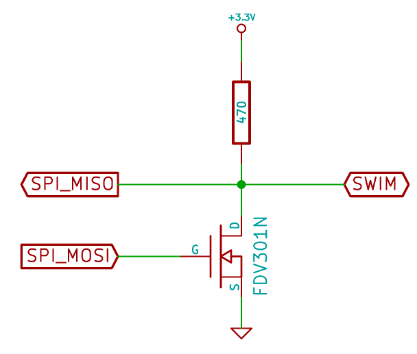
The resistor was chosen to provide minimum recovery time while staying within the 8mA current limit at 3.3V Vcc. The (field-effect-) transistor was chosen from the ones I've had on hand. It is important to pick a transistor which can turn off quickly, otherwise any low pulse will be prolonged. First I've tried with a BC547, but it would stay turned on too long when saturated (It could be improved with some bias voltages but I was too lazy to experiment with that).
The transistor configuration works as an inverter, so that driving MOSI high pulls SWIM low. The MISO line monitors SWIM directly, so that it will receive any bits transmitted by the Pi or the STM8. Transmitting a sequence of bits on MOSI without the STM8 attached should in theory return the same sequence, inverted, on MISO. In reality, the transistor's turn-off time turned out to be skewing the results, extending each low-level period considerably. My software works with a simple work-around - the low periods are simply transmitted shorter than required. It sucks, but it works.
SoftwareTop
The programming software accesses SPI using the Linux spidev driver (/dev/spidev#.#). The driver allows programs to send out a reasonably long buffer of bytes and simultaneously receive the response into another buffer. The software fills the SPI buffer using three primitives:
- transmit low speed bit 0
- transmit low speed bit 1
- transmit nothing, making space for the STM8 to send one low speed bit (plus some margin)
Analogously, the received buffers are interpreted as low-speed bits 0/1, skipping the parts transmitted by us to recover data transmitted by the STM8.
Based on these primitives, SWIM operations such as ROTF (read-on-the-fly) and WOTF (write-on-the-fly) can be implemented. An example transmission is shown below. Abbreviations: a - ack, X - the host sends a "space" instead of 0/1 bit
| operation | Pi: Read 1 byte from 0x123456 | STM: 0x78 | |||||||||||||||||||||||||||||||||||||||||||||||||||||||||||
|---|---|---|---|---|---|---|---|---|---|---|---|---|---|---|---|---|---|---|---|---|---|---|---|---|---|---|---|---|---|---|---|---|---|---|---|---|---|---|---|---|---|---|---|---|---|---|---|---|---|---|---|---|---|---|---|---|---|---|---|---|---|
| SWIM (Pi->STM) | ROTF | 1 | 0x12 | 0x34 | 0x56 | a | |||||||||||||||||||||||||||||||||||||||||||||||||||||||
| ls bits (output) | 0 | 0 | 0 | 1 | 1 | X | 0 | 0 | 0 | 0 | 0 | 0 | 0 | 0 | 1 | 1 | X | 0 | 0 | 0 | 0 | 1 | 0 | 0 | 1 | 0 | 0 | X | 0 | 0 | 0 | 1 | 1 | 0 | 1 | 0 | 0 | 1 | X | 0 | 0 | 1 | 0 | 1 | 0 | 1 | 1 | 0 | 0 | X | X | 1 | |||||||||
| SWIM (STM->Pi) | a | a | a | a | a | 0x78 | |||||||||||||||||||||||||||||||||||||||||||||||||||||||
| ls bits (input) | 0 | 0 | 0 | 1 | 1 | 1 | 0 | 0 | 0 | 0 | 0 | 0 | 0 | 0 | 1 | 1 | 1 | 0 | 0 | 0 | 0 | 1 | 0 | 0 | 1 | 0 | 0 | 1 | 0 | 0 | 0 | 1 | 1 | 0 | 1 | 0 | 0 | 1 | 1 | 0 | 0 | 1 | 0 | 1 | 0 | 1 | 1 | 0 | 0 | 1 | 1 | 0 | 1 | 1 | 1 | 1 | 0 | 0 | 0 | 0 | 1 |
The host prepares a SPI buffer with the following operations:
- Send out a low-speed-bit sequence representing the "ROTF" (read-on-the-fly) operation.
- Make some space to receive an acknowledgement from the STM (X)
- Assume that the ack ('1' low-speed-bit from the STM) was received correctly. This will be verified only after the whole buffer is transferred and response is received.
- Send subsequent data bytes (1, 0x12, 0x34, 0x56) making space for acks.
- Make some more space to receive the response byte from the STM.
- Preemptively send an acknowledgement confirming that the data was received correctly.
After the I/O is performed, the response buffer is scanned for ack's, and responses. Occasionally, STM doesn't acknowledge these operations properly, I assume that it's because of timing disruptions mentioned above. In such case, the operation is simply retried.
ROTF and WOTF operations, in turn, allow the whole flash programming procedure to be performed. See the manufacturer's documentation or source code for the boring details.
Source codeTop
I've used stm8flash as the base for my programming software. The original code supports SWIM, although only using the ST-LINK hardware. I've extended it to support SPI-based SWIM programming, and uploaded my version to github.
I don't have any experience with debugging over SWIM. A brief look at the datasheets suggests that the debugging protocol is based on simple register reads/writes, so theoretically this wouldn't be any more difficult than the flash programming part. I wouldn't attempt to "roll my own" debugger, but OpenOCD claims to support SWIM (using an st-link USB adapter). If you are interested in a working debugger, that's where you should look.
On the other hand, if you wish to use my SPI hack (why?:), you could just replace the USB-based transport in OpenOCD with my SPI code and it should "just work".
the only thing is: most people would be very reluctant to also have to buy an STLinkv2 in addition to the sensors, just to *maybe* reprogram it, so what you've done here is actually very very important. the possibility exists to port this version stm8flash onto an Arduino, or actually integrate it into Marlin or RepRapFirmware as a way to upload new firmware binaries to the various sensors.
however (ab)using SPI would be... quite awkward, as those particular pins would not necessarily be available. would you be interested to help make a GPIO bit-banging equivalent of the SPI functions? so that a user could simply... pick absolutely any spare GPIO pins, one for reset and one for SWIM?
A bit-banging implementation of SWIM would probably be simpler than trying to use SPI. Also, you could try to skip the transistor and use the GPIO in a pseudo-open-collector mode, basically switching between output-low and input mode.
I'm not sure if my code will be very useful for you, maybe more as an inspiration. The SWIM protocol is quite simple and implementing it in bit-banging mode should not be very troublesome. The only issue would be the frequency. If you mean to run it on a 16MHz AVR, that would mean producing/consuming one bit in two clock cycles == two instructions. Forget about timers and interrupts - for such tight timing you would need hand-written assembly. It seems possible - the bit states don't change that often so you could squeeze in some logic between the GPIO state switching, but it's certainly not a trivial task.
I don't have much free time these days, so I can't offer any "hands-on" help, but if you have any further questions feel free to ask.
I need to program STM8 (STNRG388A) using mbed LPC1768, can i use your source code and related stuff?
Waiting for your positive response.
Anyway, feel free to use anything you like. The source code is available on github (see link at the top of the page) under GPLv2.
"Determine FLASH area
Could not communicate with target
Error communicating with MCU. Please check your SWIM connection."
Can I use AO3442 or NX7002AK instead of FDV301N since I have these two in my hands?
A quick check reveals that AO3442 is a high-current device and has *huge* capacitances compared to the FDV, and it will limit the switching speed. Its threshold voltage is also quite high, meaning that it takes more to turn on. The NX7002 should be a better choice, although still somewhat worse than the FDV301N.
I only have a IRLML2502 and a IRF7807ZTRPBF N Channel Mosfet available.
I tried the first one (IRLML2502) with a 470 ohm resistor on a rpi3B+
My logic analyzer can see RST going low and some traffic on MISO but it doesn't seem to work (ive debugged the sync value) :
./stm8flash -c spi -p stm8s003?3 -w test.ihx
Determine FLASH area
sync = 0
sync = 1
sync = 1
sync = 1
Could not communicate with target
Do you think the mosfet is not fast enough ?
[root@Nscreen64:/boot]# stm8flash -c spi -p stm8s003f3 -w firmware.hex
Determine FLASH area
CMD >.001.01-.000.000.001.1-.000.000.000.0-0.0111.111.11.-01.000.000.01.-01.010.000.00
RSP >.001.01-.000.000.001.1-.000.000.000.0-0.0111.111.11.-01.000.000.01.-01.010.000.00...........
(retrying write command)
CMD >.001.01-.000.000.001.1-.000.000.000.0-0.0111.111.11.-01.000.000.01.-01.010.000.00
RSP >.001.01-.000.000.001.1-.000.000.000.0-0.0111.111.11.-01.000.000.01.-01.010.000.00...........
(retrying write command)
CMD >.001.01-.000.000.001.1-.000.000.000.0-0.0111.111.11.-01.000.000.01.-01.010.000.00
RSP >.001.01-.000.000.001.1-.000.000.000.0-0.0111.111.11.-01.000.000.01.-01.010.000.00...........
(retrying write command)Fatal SWIM Communications error
Writing binary file 8192 bytes at 0x8000...
CMD >.001.01-.000.000.001.1-.000.000.000.0-0.0111.111.11.-01.000.000.01.-01.010.000.00
RSP >.001.01-.000.000.001.1-.000.000.000.0-0.0111.111.11.-01.000.000.01.-01.010.000.00...........
CMD >.001.01-.000.000.001.1-.000.000.000.0-0.0101.00.000.-00.101.110.00.-011.111.11.01
RSP >.001.01-.000.000.001.1-.000.000.000.0-0.0101.00.000.-00.101.110.00.-011.111.11.01...........
(retrying write command)
CMD >.001.01-.000.000.001.1-.000.000.000.0-0.0101.00.000.-00.101.110.00.-011.111.11.01
RSP >.001.01-.000.000.001.1-.000.000.000.0-0.0101.00.000.-00.101.110.00.-011.111.11.01...........
(retrying write command)
CMD >.001.01-.000.000.001.1-.000.000.000.0-0.0101.00.000.-00.101.110.00.-011.111.11.01
RSP >.001.01-.000.000.001.1-.000.000.000.0-0.0101.00.000.-00.101.110.00.-011.111.11.01...........
(retrying write command)Fatal SWIM Communications error
stm8flash: spi.c:254: spi_transact: Assertion `rcvlen >= bb->cur - buf' failed.
Aborted
The next step would be to observe the signals with an oscilloscope or at least a logic analyzer.